
Concrete Scanning on a Post-Tension (PT) Slab
Reduce risk before drilling, coring, cutting, or anchoring into post-tension concrete.
Concrete Scanning on Post-Tension Slabs
Concrete scanning on post-tension (PT) slabs is performed using ultra-high frequency ground penetrating radar (GPR) to non-destructively locate embedded reinforcement within concrete structures. This includes the profile and position of post-tension tendons, reinforcing steel, and other internal elements that may be impacted during drilling, cutting, or coring operations.
Before performing any intrusive work, scanning is strongly recommended to help reduce the risk of striking stressed PT cables or reinforcement, which can pose serious safety hazards and result in costly structural damage.

GPR Scanning Methods for PT Slabs
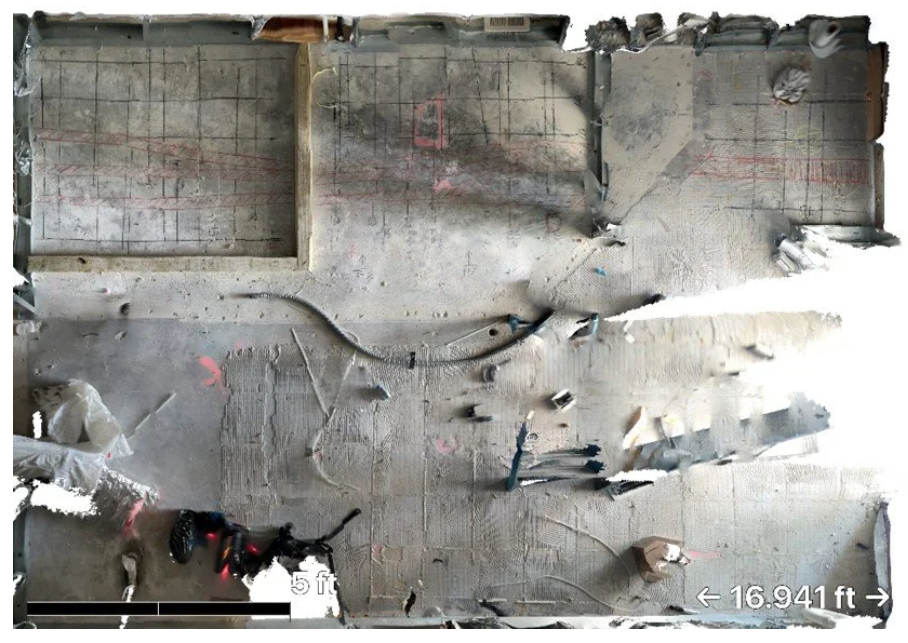
Aerial view of concrete slab showing GPR scan markings identifying reinforcement and post-tension cable locations.
There are two primary GPR scanning approaches used depending on project needs, access, and required level of documentation.
Real-Time (2D) GPR Scanning
In real-time scanning, the field technician performs 2D line scans across the concrete surface. The collected radar data is interpreted on site, and detected reinforcement is marked directly on the surface of the slab.
This approach:
Is efficient and fast
Provides immediate field guidance
Is commonly used for standard coring, drilling, and cutting layouts
The final output is a clearly marked reinforcement layout visible on the concrete surface.
Grid-Based (3D) GPR Scanning
For projects requiring enhanced visualization or documentation, 3D GPR scanning may be performed. In this method, the scan area is established by the client or their representative, and data is collected using a formal grid pattern, typically with scan intervals ranging from 2 to 6 inches in both directions.
This method produces a digital representation of the concrete slab, which may indicate:
Reinforcement patterns
Post-tension cable profiles
Steel rebar layout
Slab thickness (where conditions allow)
3D scanning results can be used for as-built documentation, planning, and further evaluation when required.
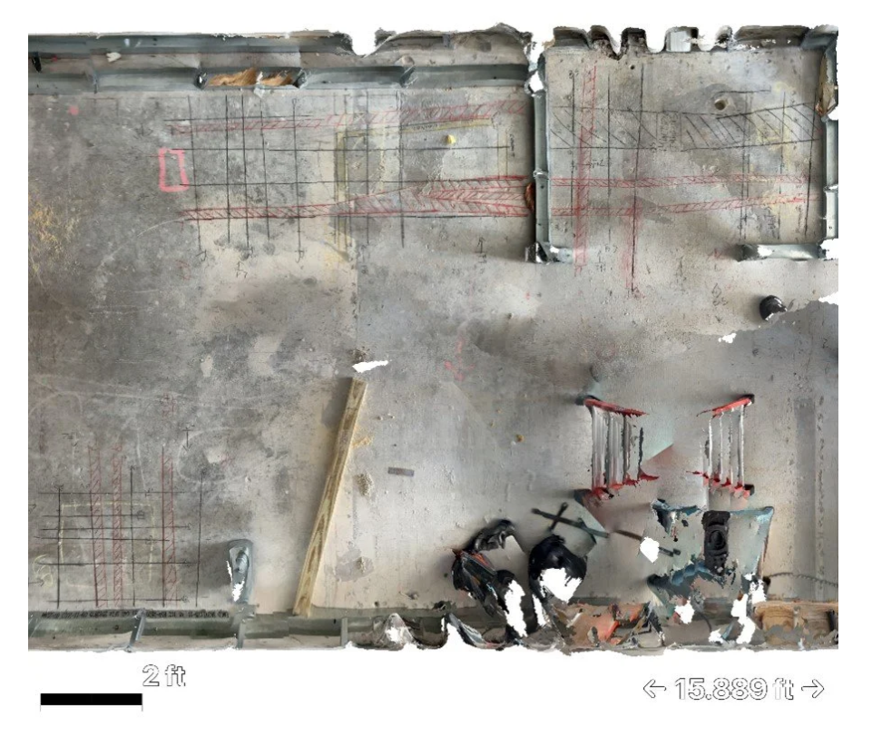
Real-time GPR scanning results with surface markings showing post-tension cables and rebar layout for safe coring and cutting operations.
Choosing the Right Scanning Approach
The selection between real-time (2D) and grid-based (3D) scanning depends on:
Project complexity
Required level of detail
Documentation needs
Risk tolerance
Schedule constraints
OmniVueNDT works with project teams to select the most appropriate scanning approach for each application.
Typical Deliverables
Depending on project scope and scanning method, OmniVueNDT deliverables may include:
Surface markings identifying detected reinforcement and post-tension tendons
Field sketches and photo documentation
Depth estimates where feasible
Optional digital outputs such as CAD or PDF files for record documentation
Deliverables are tailored to project requirements and site conditions to support safe and informed decision-making.
Important Considerations
Ground penetrating radar is a non-destructive, interpretive technology, and results may vary depending on concrete composition, reinforcement density, moisture conditions, and site accessibility. GPR scanning does not replace structural engineering evaluation, and final decisions regarding drilling, cutting, or coring locations remain the responsibility of the project team.
OmniVueNDT emphasizes clear communication of findings, confidence levels, and limitations to support informed decision-making and risk mitigation.
Planning to Drill, Core, or Cut a PT Slab?
Early concrete scanning helps reduce risk, prevent costly damage, and improve jobsite safety.